GTR Transformers
Transformer Condition Assessment. Knowledge ‘is’ Power
“GTR believe extending the useful life of a power transformer is the single most important strategy for increasing life of power transmission and distribution infrastructure”
Determining the present condition of a power transformer is an essential step in analysing the risk of failure.
Reasons for Assessment
For providing reliable electrical
energy, it is very necessary to have
highly reliable associated electrical
equipment. The transformer, being a
key element in the transmission and
distribution of electrical energy,
improving its reliability is of utmost
importance. System abnormalities,
loading, switching and ambient
condition normally contributes
towards accelerated aging and
sudden failure, Hence, it is, all the
more essential, to employ on-site
diagnostics followed by quality
maintenance for trouble-free and
reliable operation with minimum
outages.
The cost of failure;
Power transformers are often
situated at strategically critical
locations in power supply systems,
and as a result the financial
consequences of their failure can
easily exceed their actual asset value.
The real challenge lies in
implementing the right action at the
right time.
Given that the average age of power
transformers in most countries is
around 25–30 years and considering
the increase of the typical failure
probability with the transformer age,
action clearly needs to be taken to
ensure their continued reliability and
functionality.
Trafo Assessment areas
Common Failure areas
The following are the major components, which have a direct bearing on reliability of the transformer
Windings and electrical circuit
• Core and clamping structure
• Bushings and external connections
• OLTC On Load Tap Changers
• Cooler equipment and cooling medium
• Control and supervisory equipment
Transformer diagnostic techniques
Several transformer diagnostic techniques are used by GTR onsite to determine the matured transformer life expectance & health. They can be grouped into Electrical tests applied to the transformer active part on-site and Insulating Oil extracted for laboratory analysis.

Evaluation for Analysis
GTR Transformers are able to
evaluate previous Transformer
maintenance records including oil
analysis samples along with a visual
external inspection to determine
which units are showing signs of
degradation and vulnerability.
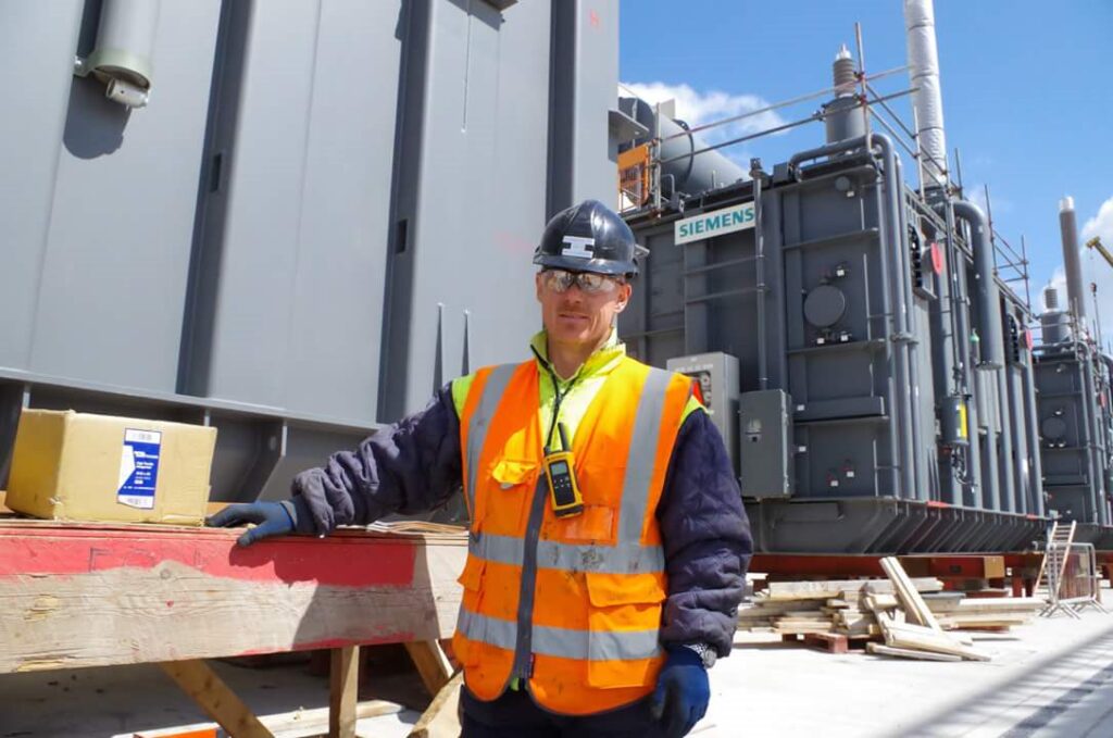
When a unit has been selected for
analysis our experienced engineers
equipped with the latest industry
leading technology will arrive at your
facility and perform onsite tests and
conduct oil sampling from various
locations using expert methods to
ensure accuracy of reporting.
GTR transformers will analyse the
collected measurements in house
providing the customer with a life
expectance in present state and
recommendations of extending life.
Identify weaknesses to manage and
control or plan for mitigating
measures.
Our software delivers comprehensive
reports to ensure future condition
monitoring has an accurate reference
to benchmark.
Onsite measurements
Transformer Condition Indicator – Electrical Tests
Turns Ratio Test
The transformer turns ratio (TTR)
test detects shorts or severe
tracking between turns of the same
coil, which indicates insulation
failure between the turns. These
tests are performed with the
transformer de-energised and may
show the necessity for an internal
inspection or removal from
service.
Short Circuit Impedance
Percent Impedance or Leakage
Reactance, these tests are
conducted in the field and
compared to nameplate
information, previous tests, and
similar units to detect deformation
of the core or windings caused by
shipping damage, through faults, or
ground faults. Some difference
may be expected between
nameplate and field test results
because factory tests are
conducted at full load current.
Field connections, test leads and
jumpers also play a significant role
in test results and it is impossible
to exactly duplicate the factory test
setup.
Core-Ground Resistance Test
The transformer core is
intentionally grounded through
one connection. The core-toground resistance test can detect if
this connection is loose. It can also
detect whether there are other
undesired and inadvertent,
grounds. If the intentional core
ground is intact, the resultant
resistance should be very low. To
check for unintentional core
grounds, remove the intentional
ground and megger between the
core and the grounded
transformer tank. This test should
produce very high resistance,
indicating that an unintentional
ground is not present. This test is
to supplement dissolved gas
analysis that shows generation of
hot metal gases (i.e., methane,
ethane, and ethylene) and to
indicate if a spurious, unintentional
core ground is the problem.
Experience can help locate the
source of the problem.
Windings Insulation Resistance
This basic insulation resistance
test is used to determine the
integrity of windings and the
condition of windings insulation.
Transformer windings are exposed to environmental factors such as
dirt, grease, temperature, stress,
and vibration which can lead toinsulation failure. The test is
performed after the initial
installation of transformer and as
part of the routine maintenance.
Winding DC Resistance Measurement
GTR Transformers are able to
evaluate previous TransformerCareful measurement of winding
resistance can detect broken
conductor strands, loose
connections, and bad contacts in
the tap changer. Results from
these measurements may indicate
the need for an internal inspection.
This information supplements
dissolved gas analysis (DGA) and is
useful when DGA shows generation
of heat gases (i.e., ethane, ethylene,
methane). Test results are
compared between phases or with
factory tests. When comparing to
factory tests, a temperature
correction must be employed.
Furthermore, OLTC dynamic
resistance can be measurement to
determine the contact resistance.
maintenance records including oil
analysis samples along with a visual
external inspection to determine
which units are showing signs of
degradation and vulnerability.
When a unit has been selected for
analysis our experienced engineers
equipped with the latest industry
leading technology will arrive at your
facility and perform onsite tests and
conduct oil sampling from various
locations using expert methods to
ensure accuracy of reporting.
GTR transformers will analyse the
collected measurements in house
providing the customer with a life
expectance in present state and
recommendations of extending life.
Identify weaknesses to manage and
control or plan for mitigating
measures.
Our software delivers comprehensive
reports to ensure future condition
monitoring has an accurate reference
to benchmark.
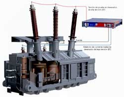
Frequency Response Analysis
Frequency Response Analysis
(FRA) or Sweep Frequency
Response Analysis (SFRA) can
determine if windings of a
transformer have moved or
shifted. It can be done as a factory
test prior to shipment and
repeated after the transformer is
received on site to determine if
windings have been damaged or
shifted during shipping. This test
is also helpful if a protective relay
has tripped or a through fault,
short circuit, or ground fault has
occurred
A sweep frequency is generally
placed on each of the high voltage
windings and the signal is detected
on the low-voltage windings. This
provides a picture of the frequency
transfer function of the windings.
If the windings have been
displaced or shifted, test results
will differ markedly from prior
tests. Test results are kept in
transformer history files so they
can be compared to later tests.
Results are determined by
comparison to baseline or previous
measurements or comparison to
units of similar design and
construction.
The power factor value of 0.5%
was used as acceptance criteria for
new transformers. Sudden
increases in value of power factor
over time are taken as a sign of
deterioration of the insulation
condition. The power factor on
serviced-aged transformer in good
condition should be in the range of
0.5% to 1.5%
Insulation power factor test of windings and bushings
Power factor is a ratio of dielectric
loss (or watt loss) to the charging
volt-amperes (or apparent power
input). It is a property of the
electrical insulation system and a
measure of the electrical losses in
the insulation when subjected to
an applied alternating voltage.
Power factor testing is the single
most valuable method of obtaining
data for determining insulation
quality. A high loss may indicate
problems in the insulation
structure. Normal ageing of an
insulating material will also
cause dielectric loss to increase.
Contamination of insulation by
moisture or chemical substances
may cause losses to be higher than
normal.
Dielectric Frequency Response
DFR also known as ‘Polarisation
Spectrum Measurement’ is used to
assess the moisture content of the
cellulose insulation located
between the primary and
secondary winding. This test is
normally carried out as part of the
maintenance routine to assess
insulation conditions. Insulation
performance can be affected by
paper aging or increased moisture
level due to broken seals. This
measurement is also used for new
transformers to prove the low
moisture content after the drying
process.
Degree of Polymerisation
Frequency Response Analysis
(FRA) or Sweep Frequency
ResponsWinding insulation (cellulose)
deterioration can be quantified by
analysis of the Degree of
Polymerization (DP) of the
insulating material. This test gives
an indication of the remaining
structural strength of the paper
insulation and is an excellent
indication of the remaining life of
the paper and the transformer
itself. This requires analysing a
sample of the paper insulation in a
laboratory to determine the
deterioration of the molecular
bonds of the paper.
e Analysis (SFRA) can
determine if windings of a
transformer have moved or
shifted. It can be done as a factory
test prior to shipment and
repeated after the transformer is
received on site to determine if
windings have been damaged or
shifted during shipping. This test
is also helpful if a protective relay
has tripped or a through fault,
short circuit, or ground fault has
occurred

Partial Discharge
Partial discharge (PD) can cause
irreversible damage to power
transformer insulation,
long before the insulation actually
fails. Even upon detection and
analysis, it is
essential to know exactly where
insulation defects are located in
the transformer.
GTR Transformers perform PD
Online diagnostics without the
need for outage using the latest
technology.
Oil analysis
Transformer Condition Indicator – Insulating Oil
Dissolved gas analysis is the most
important factor in determining the
condition of a transformer. Being
performed more frequently than
other tests, it may be the first
indication of a problem. Insulating oil
analysis can identify internal arcing,
bad electrical contacts, hot spots,
partial discharge, or overheating of
conductors, oil, tank, or cellulose.
The “health” of the oil reflects the
health of the transformer itself.

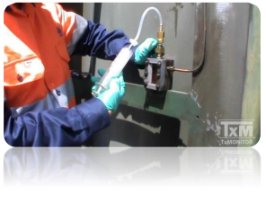
Dissolved gas analysis (DGA) consists
of drawing transformer insulating oil
samples from the transformer tank
and sending the samples to a
commercial laboratory for analysis.
The most important indicators are
the individual and total dissolved
combustible gas (TDCG) generation
rates, based on IEC and IEEE
standards. Although gas generation
rates are not the only indicator, they
are reasonable for use in determining
the condition indicator score.
Furanic analysis may indicate a
problem with the paper insulation
which could affect transformer
longevity. A baseline furanic analysis
should be made initially and repeated
if the transformer is overheated,
overloaded, aged, or after changing or
processing the oil.
Physical tests such as interfacial
tension (IFT), acidity, moisture
content, and dielectric strength
usually indicate oil conditions that
can be remedied through various
reclamation processes. Therefore,
they are not indicative of overall
transformer condition that would
lead to replacement.